4.1 Materials
- Select the Material Editor
 in the tool palette, press ⌘L on your keyboard, or select Show Materials under the Materials Menu. to view the materials assigned to the current drawing stage, add new materials, or remove existing materials.
- Add a new material to the current drawing stage by clicking the + button at the bottom of the material editor.
- Remove an existing material from the current drawing stage by clicking the - button at the bottom of the material editor.
- Edit an existing material in the drawing by double clicking the row of the material in the material editor.
- Once a material is added, it is available to be used to fill a region. The material can also be saved to the Material Library for later use, by clicking the Add to Library button at the bottom right of the editor.
Material Library
- Select Show Materials Library from the Materials Menu, or press ⌘L on your keyboard to view, add, edit, and remove materials in the material library.
Material Types
MacSlope allows the following material types to be defined:- Soil - materials defined using the Mohr-Coulomb strength parameters c' and Φ '. Total Unit Weight must also be specified.
- No Strength - materials which have unit weight, but have no strength and through which slip surfaces pass vertically. Used to model fluids such as water.
- Impenetrable - materials through which slip surfaces can not penetrate. Strength and unit weight parameters are ignored. Used to model hard layers such as bedrock.
Strength with Depth
- A strength variation with depth for the cohesion (c) and friction (Φ) parameters may be specified for Mohr-Coulomb materials, as follows:
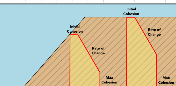
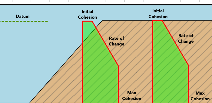
- Initial Cohesion - starting value of cohesion at the top of layer or datum point as specified. (kPa) or (psf)
- Δ Cohesion - rate of change with depth of the cohesion parameter. (kPa/m) or (psf/ft)
- Maximum Cohesion - limiting maximum value of cohesion parameter at depth. (kPa) Leave it set to 0 for no limit.
- Initial Friction - starting value of friction angle at the top of layer or datum point as specified. (deg)
- Δ Cohesion - rate of change with depth of the friction parameter. (deg)
- Maximum Friction - limiting maximum value of friction angle parameter at depth. (deg). Leave it set to 0 for no limit.
- Relative to - elevation at which the strength change begins, measured either to the top of layer or specified datum. See figure 1a and 1b below.
- Datum - specified datum elevation from which to measure strength change of cohesion/friction parameters. (m) or (ft)

Figure 1a - Strength increase measured relative to top of layer

Figure 1b - Strength increase measured relative to specified datum elevation
Anisotropy
- Anisotropic strength parameters for Mohr-Coulomb materials may be specified using the transverse isotropic model, or by defining custom ranges of slice base angles for which anisotropic parameters apply.
- The Transverse Isotropic model gives the available strength a smooth transition between two sets of parameters that are orthogonal to each other (90 degrees). The cohesion and friction angle are calculated depending on the slice base angle as follows:
- Alternatively, you can Define Anisotropic Ranges, specifying the available cohesion and friction over specific ranges of slice base inclination, where the angles are defined from -90 to +90 degrees, where 0 represents the horizontal. It is not necessary to define the entire range of angles, if a slice falls outside the specified ranges the default cohesion and friction values for the material are used.
- Note: In MobiSlope, slice base angles are defined depending on the direction of slip. For left to right slips, positive angles are measured from the negative x-axis, while for right to left slips, positive angles are measured from the positive x-axis. The result is that for all slips, positive slice base angles generally correspond to driving (active) slices, while negative slice base angles generally correspond to resisting (passive) slices. This is useful to keep in mind while defining material anisotropy using either method.


Pore Pressure Conditions
- Pore pressure conditions may be specified for each material by a pore pressure coefficient, ru or B-bar, or by use of a piezometric surface, discussed in detail in the Pore Pressure Conditions section.
Statistical Distributions
- Statistical distributions can be assigned to various parameters for probabilistic analysis. These parameters include unit weight, cohesion, friction, ru, B-bar, and the strength with depth and anisotropic parameters.
- Tap the
 icon next to an available parameter to assign it a statistical distribution. The icon turns blue
  next to parameters that have statistical distributions assigned. See more on statistic distributions and probabilistic analysis in probabilistic analysis.
Material Colors and Patterns
- A color and pattern may be assigned to each material by selecting the Color/Pattern field in the detail material editor.