6.3 Slip Surface Optimization
- Initial # Vertices - The initial number of vertices that define the slip surface. (Integer greater or equal to 4)
- Δ # Vertices - The number of vertices to add to the slip surface definition at the end of the current exploration phase. (Integer greater or equal to 1)
- Final # Vertices - The number of vertices required in the slip surface to arrest the optimization procedure. (Integer greater than the initial # vertices)
- Initial Step Size - The initial step size of the random walk movement, normalized for the current distance between vertices, defined as a number greater than 0 and less or equal to 0.8. The step size is limited to 0.8 to prevent interference between close vertices.
- Δ Step Size - The change in step size of the random walk movement.
- Final Step Size - The step size required for all vertices to arrest the exploration phase in the optimization procedure, less than the initial step size.
- Max Concave Angle (deg) - The maximum change in slice base angle between adjacent slices in the concave direction. Specify a value in degrees greater than 0. It is recommended to leave it at the default (90 deg), unless sharp kinks which are not kinematically feasible are observed in the optimized slip surface.
- Max Convex Angle (deg) - The maximum change in slice base angle between adjacent slices in the convex direction. Specify a value in degrees greater than or equal to 0. A value of 0 does not permit any convexity in the slip surface.
- 1. The current number of vertices are interpolated along the starting slip surface evenly, and the slip surface is redefined by straight line segments between these vertices.
- 2. An "exploration" phase takes place whereby for every vertex in the slip surface definition:
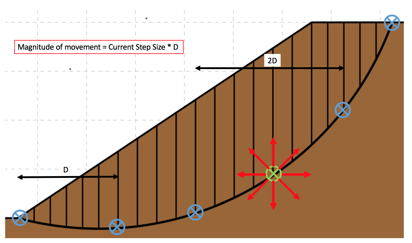
- 2a. The vertex is moved randomly using the current step size (up to 8 different directions are attempted), as shown in Fig 1 below.
- 2b. Slice boundaries are added to meet geometrical constraints and maximum slice width criteria.
- 2c. The FOS is calculated for the new slip surface.
- 2d. If the new FOS is lower than the existing FOS, the new vertex position is retained and the step size increases (by the specified Δ) for this vertex. Otherwise, the vertex returns to it's original position and it's step size decreases (by the specified Δ).
- 2e. The arrest criterion for the exploration phase is checked. The current step size for every vertex in the slip surface must be equal to or less than the final step size.
- We now have an optimized slip surface (ie. the FOS is less than or equal to the starting value), but there are two potential problems. The first is if the slip surface is defined by an insufficient number of vertices, it may not represent the true optimized FOS for the problem. The second potentional problem occurs when the initial number of vertices is too great, the vertices can not mutate efficiently to find the critical slip surface due to the small distance between them. Li and White (1987) proposed an initial search with few vertices, and gradually adding vertices to the slip surface to improve the accuracy. The arrest criterion in the MobiSlope implementation of the optimization process checks the current number of vertices in the slip surface definition, and if it is less than the final number of vertices, the Δ # Vertices are added to the current number of vertices, and we return to step 1, but the starting slip surface is now the optimized slip surface.
- To cancel an optimization in progress, select Cancel Optimization from the Optimization menu
 .
. - No controls are placed on the random walk movement of the vertices, other than the step size. As a result, physically inadmissible slip surfaces are sometimes generated.
Notes on the optimization implementation
- To prevent this, trials are rejected that do not satisfy the constraints proposed in Greco (1996) that mα >= 0.2 and pα >= 0.4 for all slices, where:
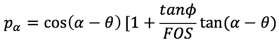
and ϴ is the inclination of interslice forces with respect to the horizontal.
Despite this, the optimization procedure may produce obviously inadmissible slip surfaces. In this case, the Max Concave Angle and Max Convex Angle values can be specified to control the permissible shape of the slip surface.
- The optimized slip surface is updated in the drawing during the optimization procedure, while the original slip surface is drawn in grey. If Show Animation is enabled in display preferences, the individual vertex mutations are displayed, however this will slow down the optimization process considerably.
- The optimization method is based on a random process, therefore differing optimized slip surfaces may be expected for the same initial starting slip surface, although this can be partially mitigated by specifying small changes in the Δ values.
- Additionally, the method is dependent on the position of the starting slip surface, and there is no guarantee that the slip surface with the true optimized minimum FOS for the problem will be located.
- Trials that have already been optimized can be optimized again to search for a further reduction in FOS, starting with the already optimized slip surface.