4.3 No Strength Materials and Submerged Slopes
- MacSlope allows for slopes to modeled as partially or fully submerged.
- Create the desired geometry and fill the intended fluid region(s) with a no strength material.
- The ground surface lines drawn in bold will automatically be detected to follow soil regions below the no strength region.
No Strength Materials
- To create a no strength material, use the material editor tool
 as discussed in the Materials section, and select the material type to be No Strength.
- Unit weight must be specified. All strength and pore pressure parameters are ignored.
- Fluids of different density than water can be modeled by altering the unit weight of the no strength material. Recall that piezometric surfaces create pore pressures using the Unit Weight of Water parameter set in the Units tool, and that the unit weight of the no strength region generally should be equal to the Unit Weight of Water parameter.
- Underlying soil regions must account for the intended pore pressure conditions, through the use of piezometric surfaces or pore pressure coefficients as discussed in Pore Pressure Conditions. A typical scenario where the pore pressure matches the the ponded water level is shown in the figure below.
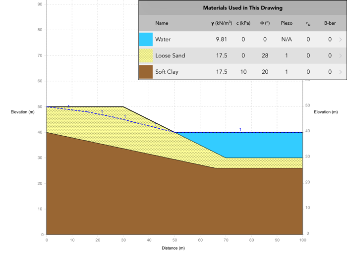
Typical scenario with ponded water
External Water Forces
- MacSlope provides two methods to model the external water forces acting on submerged slopes:
- Include No Strength Regions in Slice
- Apply Hydrostatic Force to Top of Slice
- The two methods will produce different internal forces (interslice normal and interslice shear) over the slip segment due to the different slice geometries created. However, the calculated factor of safety will be very similar for both methods owing to the fact that the interslice forces must cancel each other out when considered over the entire slip segment.
- To change the method used for submerged slopes, click Analysis Settings
 in the tool palette, then select Advanced Settings.
Method 1: Include No Strength Regions in Slice
- MacSlope includes the no strength regions in the slice geometry for analysis.
- No strength regions contribute to the weight of the slice.
- Slip surfaces pass vertically through no strength materials when encountered.
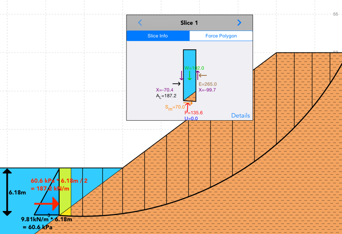
- Where a no strength region is encountered at the boundary of a slip surface, an external force is added to the side of the boundary slice, representing an external fluid force. The calculation for the external fluid force is depicted in the figure below.
- Once an analysis is complete, use the Inspector Tool and click over a boundary slice adjacent to a no strength region to view the slice forces and verify the lateral fluid force has been modeled as expected. You can perform a simple calculation to check as shown in the figure below.
Method 2: Apply Hydrostatic Force to Top of Slice
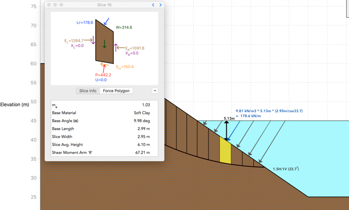
- MacSlope applies a hydrostatic force normal to the top of the slice, due to the weight of the no strength region above the ground surface, as depicted in the figure below.
- Note that only one no strength region may be specified above the ground surface at any given x coordinate (ie. no layered fluids).
- When using ru coefficients to model pore pressure, the vertical component of the hydrostatic force is added to the slice weight to replicate the weight of the fluid column above the slice.
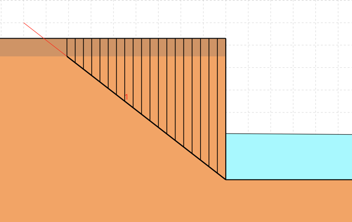
Special Case for Vertical Slope
- Beginning in MacSlope v1.5, for the case shown below where a vertical slope has ponded fluid at the toe, an external fluid force is added to the side of the vertical boundary slice for either method 1 or 2.