4.4 Reinforcements
- MacSlope allows for reinforcement forces to be specified in the analysis. The reinforcement forces are incorporated as external loads acting on the soil mass, and the magnitude and direction of these forces depends on how they are specified below.
- Select the Reinforcement Editor
 in the Materials / Loads tab of the tool palette to view the reinforcements assigned to the current drawing stage, and to add or remove reinforcements.
- Add a new reinforcement to the current drawing stage by clicking the + button at the bottom of the reinforcement editor.
- Remove an existing reinforcement from the current drawing stage by clicking the - button at the bottom of the reinforcement editor.
- Edit an existing reinforcement in the drawing by double clicking the row of the reinforcement in the editor.
- Once a reinforcement is added, it is available to be used to assign to a non-surface line in the drawing geometry, using the Select/Pan
 tool. The reinforcement can also be saved to the Reinforcement Library for later use, by clicking the Add to Library button at the bottom right of the editor.
 - The desired non-surface line to apply the reinforcement to must connect to the ground surface line.
Reinforcement Library
- In the file management view, tap the button at the bottom of the screen to view, add, edit, and remove reinforcements in the reinforcement library.
Reinforcement Types
MobiSlope allows the following reinforcement types to be defined:- Anchor - reinforcement with tensile, shear, and pullout capacity.
- The tensile capacity is calculated from the tensile strength specified for the anchor, the spacing between anchors, and the tensile FOS.
- The pullout capacity is calculated using the effective length and perimeter, and either an interface angle or specified resistance. The effective length is depicted as in Fig. 4.4.1.
- The specified pullout resistance is defined in units of pressure (F/L2) and applies over the perimeter of the anchor for the effective length.
- An anchor-soil interface angle can also be specified.
- The magnitude of the applied reinforcement force is the lesser of the tensile and the pullout capacity available where the slip surface intersects the reinforcement. The governing capacity (tensile or pullout) for the reinforcement is indicated in the Force Polygon summary for the relevant slice using the Inspector Tool. The variation of typical tensile and pullout capacities available along the reinforcement is depicted as in Fig. 4.4.2.
- An optional shear capacity can also be specified, and is calculated from the shear strength specified for the reinforcement, the spacing between anchors, and the shear FOS. The optional shear force acts perpendicular to the reinforcement force.

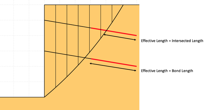
Figure 4.4.1 - Definition of Effective Length
Pullout Capacity using Specified Resistance

where: Leff = Effective Length P = Perimeter |
Pullout Capacity using Interface Angle

where: Leff = Effective Length P = Perimeter σ'v = Effective stress at midpoint of effective length φi = Interface angle between soil and reinforcement |
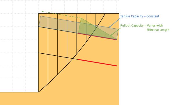
Figure 4.4.2 - Variation of Tensile and Pullout Capacity Along Reinforcement

- Geosynthetic - reinforcement with tensile and pullout capacity.
- The tensile capacity is calculated from the tensile strength specified for the geosynthetic per unit width of slope (1m or 1ft of slope), the percentage of area covered by the geogrid per unit width of slope, and the tensile FOS.
- The pullout capacity is calculated using the effective length, and either an interface angle or specified resistance. The geosynthetic bond length is assumed to be the entire length of the reinforcement. The effective length is depicted as in Fig. 4.4.1.
- The specified pullout resistance is defined in units of pressure (F/L2) and is multiplied by 2 to represent its application over each side of the geosynthetic for the effective length.
- A geosynthetic-soil interface angle can be specified for the upper and lower sides of the geosynthetic. Normally these angles would be equivalent but they could vary for geosynthetic placed between different soil layers.
- The magnitude of the applied reinforcement force is the lesser of the tensile and the pullout capacity available where the slip surface intersects the reinforcement. The governing capacity (tensile or pullout) for the reinforcement is indicated in the Force Polygon summary for the relevant slice using the Inspector Tool. The variation of typical tensile and pullout capacities available along the reinforcement is depicted in Fig. 4.4.2.

Pullout Capacity using Specified Resistance

where: Leff = Effective Length P = Perimeter |
Pullout Capacity using Interface Angle

where: Leff = Effective Length P = Perimeter σ'v = Effective stress at midpoint of effective length φi = Interface angle between soil and reinforcement |
- Pile - reinforcement with shear resistance only.
- The shear capacity is calculated using the spacing between piles, the shear FOS, and either a constant shear strength specified per unit width of slope, or a shear strength envelope which may vary along the pile.
- In the case of constant shear strength, the reinforcement force is applied at the intersection of the pile with the trial slip surface.
- In the case of a shear strength envelope, The pile shear reinforcement force is calculated by integrating the shear envelope over the length of the pile intersected by the slip surface. The force is applied at the centroid of the force envelope. Specify values of the shear force per unit width of slope at the pile head and base.

Distribution and Inclination of Reinforcement Forces
- By default the applied reinforcement force acts parallel (axially) to the reinforcement, at the position where the slip surface intersects it. The direction of the applied reinforcement forces always work to reduce the driving forces/moments.
- As an alternative to applying the entire reinforcement force at the slice base, the force can be divided evenly across all the slices that it intersects. For each reinforcement defined, the Force Distribution option can be set under the Advanced tab. Results are not known to vary widely between options, but it may be beneficial to try both options in case of convergence problems.
- Shear forces can not be distributed across intersected slices.
- The inclination of the applied reinforcement force can be changed to be between parallel to the reinforcement and parallel to the slice base. For each reinforcement defined, the Force Inclination value can be set under the Advanced tab. A value of 0 orients the force in the direction of the reinforcement, and a value of 1 orients the force parallel to the slice base (or perpendicular to the slice side where the reinforcement intersects it, if the forces are divided between the intersected slices).
- Shear reinforcement forces by default act perpendicular to the reinforcement, but also can be altered towards parallel to the slice base using the Force Inclination value. The direction of the force works to reduce the driving forces/moments.
Reinforcement Forces and Factor of Safety
- By default reinforcement forces are specified as allowable and are factored using local FOS values for the tensile, pullout, and shear components of the reinforcement, and are NOT factored by the computed FOS of the soil mass being analyzed.
- Local factors of safety for tensile, shear, and pullout components can be used to reduce the long-term capacity of the reinforcement for factors such as creep, installation damage, and durability.
- For each reinforcement defined, the Use Computed FOS option can be selected under the Advanced tab. In this case, the local factors of safety for the reinforcement component forces are ignored, and the reinforcement force components are factored by the computed FOS of the soil mass being analyzed. This option may be appropriate for reinforcements where the resistance mobilized would not act immediately but rather be dependant on movement of the soil mass.
- When the Use Computed FOS is enabled, the reinforcement force is included in the FOS calculation as follows:
- When the Use Computed FOS is disabled, the reinforcement force is included in the FOS calculation as follows:


- To ensure that the reinforcement forces considered within the analysis are as expected, it is required to inspect them using the Slice Inspector tool and using custom plots of the force and stress distributions across the soil mass. The reported magnitude of the applied reinforcement forces are per unit width of slope (1m or 1ft) as with all other forces considered.
- The user must recognize that the application of external reinforcement forces can lead to physically inadmissible distributions of the internal forces within the slices, which can lead to convergence issues in the analysis. It may be necessary to enable the Allow Base Tension, Allow Interslice Tension, and Allow Interslice Shear > Available Side Shear options under the Advanced tab of the Analysis Settings
 view.
view. - To help avoid convergence issues, it is recommended to initially reduce the specified strength values of the reinforcements and then increase them towards the desired values, while monitoring for non-convergence issues near the slip plane under consideration.
Consideration of Slope Facing
- In the FOS calculations, MacSlope does not any consider structural slope/wall facing elements used to prevent soil from sliding/spalling in between layers of reinforcement for steep slopes.
- It is thus implied that the capacity of any structural facing elements is greater than the tensile strength specified for the reinforcement, such that there is no reduction for slip surfaces passing close to the slope face.
Statistical Distributions
- Statistical distributions can be assigned to various parameters for probabilistic analysis. These parameters include tensile, shear, and pullout resistance parameters, spacing, bond length, and area coverage.
- Click the
 icon next to an available parameter to assign it a statistical distribution. The icon turns blue
  next to parameters that have statistical distributions assigned. See more on statistic distributions and probabilistic analysis in probabilistic analysis.